March 3, 2022
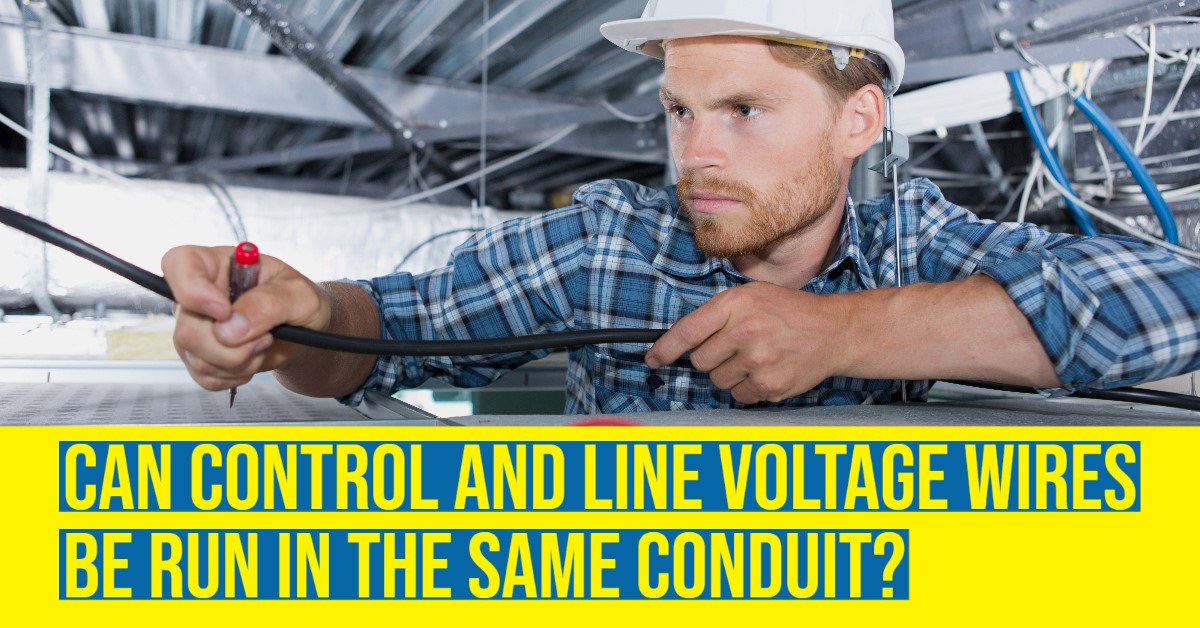
Can Control and Line Voltage Wires Be Run in the Same Conduit?
Author: C. Webster Marsh, contributor to the Lighting Controls Association
Let's explore code, safety and interference issues
With NEMA’s latest guidance and changes to 0-10V control wire colors, I want to dust off an old question: Should the control wires be run in the same conduit as the line voltage wires? When asked questions like these, my default response is: “It depends,” but in this instance we are talking about best practice. It may be more cost effective to run everything in a single conduit, or use pre-wired metal clad cable, but would I recommend this as a best practice? No, never.
To get to this answer, we should review the following considerations:
National Electric Code
Before getting started, let’s review the code requirements that matter for this discussion:
-
Class 1 wiring often refers to line voltage wiring (example for North America: 120/208VAC or 277/(347/480)VAC).
-
Class 2 wiring often refers to the wiring between the driver and the LEDs (example: 12VDC or 24VDC).
-
Per National Electric Code (NEC), Class 1 and Class 2 wiring are not permitted in the same enclosure, cable, or raceway. An exception to this rule is that Class 2 circuits can be reclassified if Class 1 requirements are met.
-
Following the above exception, control wiring may be run in the same enclosure as the line voltage. I still do not advise it and recommend that you review all pertinent codes before doing so.
Interference
The most prominent issue is electromagnetic interference (EMI), which is a kind of interference created when the performance of electrical devices and wiring is degraded because of adjacent electrical devices and wiring. When talking about lighting controls wires, we are talking about a form of EMI that impacts wired communication, either through conductivity (from physical contact) or radiation (without physical contact). EMI can be insignificant, which would create imperceptible fluctuations in performance, or EMI can be detrimental, which can result in visible flickering in the lighting or in preventing communication between devices altogether.
Electromagnetic compatibility (EMC) is the complex study of equipment and its ability to operate with EMI. I won’t belabor the intricate details of EMC, but suffice it to say there is a lot of work done just to verify EMC on devices of the same system, let alone unrelated systems. A designer is not expected to be an EMC expert, however, and so it can be hard to predict during the design phase whether interference between unrelated systems will be significant or not. As a designer, I assume unrelated wires and devices have enough interference to be detrimental or that my own system’s wiring and devices pose a threat to others, so I plan to have proper buffering where necessary.
How does a designer specify proper buffering? There are a lot of considerations, but the best tool a designer has is to specify the proper cable run. I am using the term “cable run” to refer to the bundling of cables in parallel to each other. A cable run can be exclusive to just one line voltage circuit or it can be a cable trough with dozens of different wires from unrelated systems.
Cables
Controls protocols, such as 0-10V, DALI, and DMX, often require specific types of cables and there may even be different classifications of the same cable, such as Cat5, Cat5e, Cat6, and so on. Modern wired protocols often utilize cables that consist of copper core wiring surrounded by a non-conductive shielding insulation, but the exact specifications of this wiring can vary from device to device, luminaire to luminaire, and project to project.
Some protocols are more susceptible to interference than others, but all protocols become dysfunctional with enough interference. Additionally, the amount of interference increases the closer cables are to each other. One way to protect the protocol from interference is to provide shielding around the wires, which creates a physical barrier between wires and sources of interference. It is important to keep in mind, however, that while shielded cable is commonly used, shielding also increases the cost of the cable and may be more difficult to install.
Another consideration is the conduit itself. Conduit in North America is a grounded metallic pipe that surrounds wires and cables, and which can act as a shield. A common installation practice is to tie the low voltage control wiring to the outside of the conduit. While this practice does prevent EMI from the wires inside the conduit, the low voltage control wires are still exposed to EMI outside of the conduit.
One last consideration is where cables can be exposed, such as at the splice or termination points or pendant drops for suspended luminaires. These exposure points may provide an opportunity for EMI to harm an otherwise well-shielded set of wires, so reducing these exposure points can help ensure adequate protection.
If money were no object, heavy shielding or discrete conduit paths for all wires may prevent most kinds of interference on a project, but for cost-conscious designers, shielding and conduit shouldn’t be the only way to prevent EMI. Understanding control signals, line voltages, and low voltages can help reduce project cost.
So how does line voltage wire differ from the control wires?
Power
Lighting control systems may utilize a variety of different cables and protocols to communicate, but the majority of control systems utilize low voltage direct-current (DC) power for communication. Low voltage DC power does not require thick wires and insulation and so it may use very thin wiring and insulation to cut down on cost. Thin wire and insulation, however, is more susceptible to signal interference. To compensate for signal interference, many low voltage control wires come with a default amount of shielding between the insulation and the wire or shielding around each individual wire in the cable. The default shielding is more about internal interference from the individual wires than from external interference, however.
Luminaires, on the other hand, often utilize line voltage alternating-current (AC) power. Line voltage AC wiring and insulation is thicker, which reduces signal interference, but line voltage also has a greater potential to create interference, thus negating the benefit of thicker insulation. Additionally, because of how AC power works, the interference isn’t constant, but rather it fluctuates.
Returning to the question: Should the control wires be run in the same conduit as the line voltage wires? Taking everything into account, if you plan to run the control cable in the same conduit as the line voltage cable, then you’re specifying a maximum interference scenario and should find a way to compensate for this choice.
When running line voltage and low voltage cables alongside each other, the low voltage cable has the potential to pick up that interference, so low voltage cables in general should not run parallel to line voltage cables. This is a best practice policy in the IT industry to avoid interference and is recommended in our industry, as well. It is suggested to keep a distance of 12-16″ or more between low voltage and line voltage when cables runs are parallel. If they must cross each other, it is recommended to do so at a 90-degree angle. What happens if the low voltage cable receives interference depends on the protocol.
Protocols and Interference
Analog 0-10V and phase dimming use the physical voltage to communicate intensity and so interference often results in a “dirty signal,” which may result in flickering lights. If a physical buffer isn’t an option, there are programs that can be used to smooth dirty signals and mitigate this issue.
Digital protocols such as DALI, DMX512, and RS485 use data packets to communicate. As a result, interference may cause a loss of data, which may result in erratic behavior anywhere along the data wire. Many resources promote DALI as “interference proof,” meaning there is no way to create significant interference, but in reality it is just less susceptible to interference than other protocols. It achieves this resistance to interference by reducing the rate at which packets are sent, increasing the voltage, and implementing unique encoding practices. These improvements have drawbacks, however, such as a slower speed of communication. Just like any protocol, DALI should not be a default solution for every project, but it may be a good solution where EMI is a concern.
Ethernet is much more complex, but interference usually results in slower data transfer or, under extreme interference, no data transfer. Ethernet also acts as the backbone to a building’s intranet, but in high concentrations it can also act as a source of interference on itself (referred to as crosstalk) or other communication lines. This is one of the reasons why IT groups can be sensitive to sharing cable runs with other groups, but lighting controls systems can sometimes use the building’s network, which would reduce cable quantities as well as interference.
There are other wired protocols that are less commonly used, but interference is still a consideration with them. A good lighting controls designer will confirm what will happen with interference, so that it is easier to troubleshoot during commissioning.
Conclusion
A quick Google search yields many articles on the effects of EMI interference. Because of this it is understandable why IT, A/V, and data cabling industries generally agree that buffering is required, even though it may not be a code requirement. Manufacturers may state that control wiring can be run along the line voltage wire, but my personal recommendation is not to risk it and to provide a buffer of some kind by shielding, separating the cable runs, or both. Project cost and timing may be a more important consideration, which is why products such as pre-wired metal clad cable or installation practices such as zip tying cables to the outside of conduit exist and are code compliant, but you are risking the possibility of added cost later when you specify it. Prior to specifying shared runs, it is a good idea to confirm with the manufacturer what their requirements are and do a mockup to verify functionality meets your specified intent By doing so, you can improve the success of your project and avoid added costs later.
Disclaimer: This article is for general informational purposes only. Follow all local construction & electrical codes. Please check and follow manufacturers' installation instructions.
The Lighting Controls Association is a council of the National Electrical Manufacturers Association that provides education about lighting control technology and application, including articles, videos, design awards, news, resources, and Education Express, a free, 24/7 series of online courses covering everything from technology to design to commissioning.
Don’t miss the next big lighting story…Click here to subscribe to the inside.lighting InfoLetter |